- This topic is empty.
-
AuthorPosts
-
21/10/2026 at 17:18 #152883
A vision inspection system rejects good parts when the image, the parts, or the decision logic drift apart: lighting and glare changed since validation, part presentation or position moved outside the trained envelope, focus or exposure degraded, tolerance limits were set from unrepresentative samples, or trigger timing captures the wrong moment. The first safe check is to open the rejected-part images — the system’s own evidence — and compare them against the images used at validation. Fixing false rejects starts with the image, not the thresholds.
Key Takeaways
- The rejected image is the data. Comparing reject-time images against validation images localizes the cause in minutes: darker? glare spot? part rotated? edge of frame? blurred?
- False rejects usually mean the world changed, not that the tolerances were wrong to start. New part batch surface finish, a replaced lamp, ambient light through a new skylight, a worn fixture shifting presentation.
- Tolerances are only as good as the sample set behind them. Limits trained on one production batch fail on the next batch’s normal variation — validation sets must span the intended production population.
- Trigger timing is a silent killer. The right part captured in the wrong instant (moving, half-in-frame, still decelerating) looks defective to any algorithm.
- Do not loosen tolerances to chase the reject rate. Loosening without re-validation trades false rejects for false accepts — the worse failure. Fix the image conditions or revalidate with proper samples.
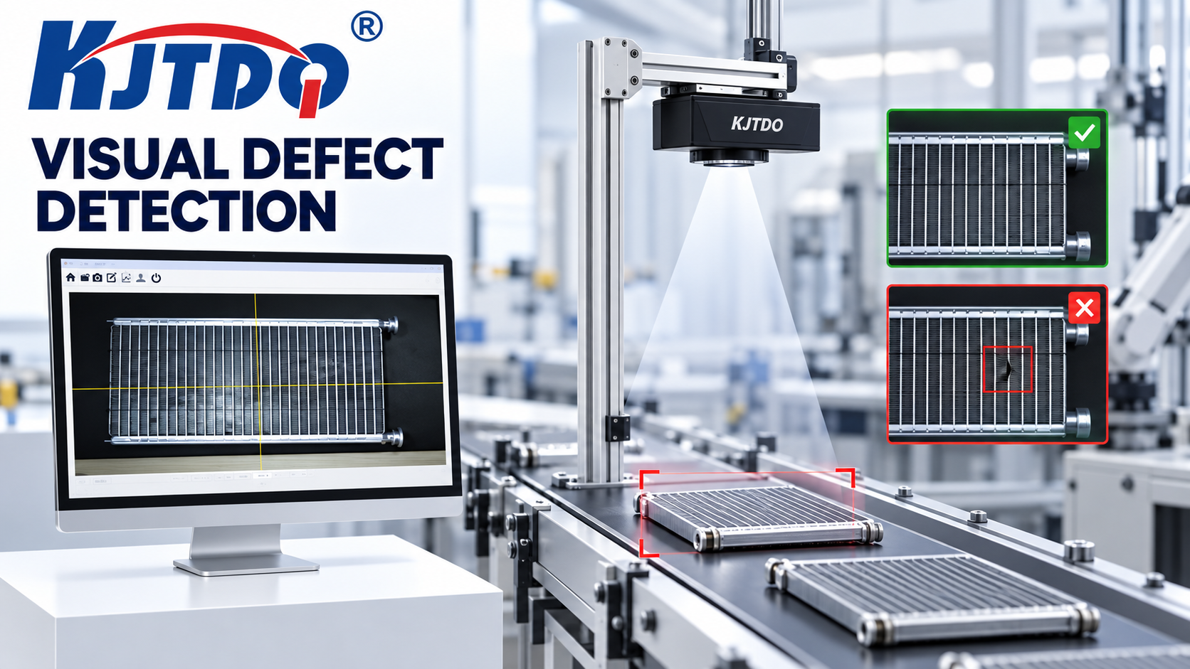
Symptom Definition
This article covers an elevated rate of rejects whose parts are confirmed good on manual review:
- Sudden step in false rejects — from a specific date or event;
- Gradual creep — slowly rising over weeks (lighting aging, fixture wear, lens contamination);
- Batch-correlated false rejects — one part batch rejects, the next passes;
- Position-correlated false rejects — parts present slightly differently reject more.
True defect detection that operators dispute (“the scratch is fine”) is a tolerance-policy question, not a false-reject fault — it needs a documented quality decision, not a technical fix.
Cause Table
Cause category Why it creates the symptom Safe check Corrective direction Technician required? Lighting change / glare Aged or replaced lamps, new ambient light, reflective new part finish — contrast and edges shift outside trained conditions Compare reject images vs. validation images; note lighting and glare differences Restore lighting to validated state; shade the station; revalidate after lighting repairs No for image review; Yes for lighting hardware Part presentation / position change Worn fixture, changed part guide, different operator loading, robot drift — features land outside the trained field of view or at untrained angles Overlay reject images with validation images: has part position/rotation drifted? Restore fixture/presentation; retrain/revalidate at the new positions if the change is permanent Yes for mechanical changes Surface finish / batch variation New supplier, new mold, new coating — normal variation falls outside limits learned from the old batch Check whether rejects cluster by batch/lot; compare surfaces under identical lighting Expand the validation sample set across batches; re-set tolerances from the full population No for analysis; Yes for revalidation sign-off Focus / optics degradation Contamination, loose lens, vibration-induced drift blur edges and shrink measured features Inspect lens/lighting covers for contamination; compare image sharpness metrics vs. validation Clean optics; re-secure lens; reverify focus per system procedure Yes for optics work Exposure / aperture drift Settings changed after maintenance, or auto-exposure chasing ambient shifts Compare exposure metadata of reject vs. validation images Restore validated exposure settings; lock exposure against ambient changes Yes for configuration Unrepresentative tolerance limits Limits set from few samples, golden-part-only validation, or manual-entry errors Audit the sample set behind current limits: count, source batches, coverage of normal variation Rebuild limits from a statistically representative good/bad sample set; document the validation Yes — validation procedure Trigger timing Capture occurs while part is moving/settling or partially in frame Review reject image sequences: motion blur, part cut at frame edge, inconsistent framing Correct trigger timing/delay per system configuration; verify at full line speed Yes for configuration Threshold / decision-logic drift Parameters edited after a maintenance session or copied from another product Review parameter change history against the reject-rate timeline Restore validated parameter set; impose change control on inspection parameters Yes Diagnostic Sequence (Least Invasive First)
- Collect and open the evidence. Export the images of falsely rejected parts plus the validation reference images. Side-by-side comparison drives the next seven steps.
- Classify the visual difference. Lighting/glare, position/rotation, sharpness, exposure, framing — each maps to a specific cause row.
- Build the timeline. Plot reject rate against events: lamp replacement, maintenance, part batch changes, season/daylight changes, fixture repairs.
- Check batch correlation. Do rejects cluster on specific lots? Surface-finish variation is then the prime suspect.
- Check position correlation. Do rejects share a position/rotation signature? Fixture or presentation drift.
- Audit the sample set. What good/bad samples set the current tolerances? Count, batches covered, and whether “good” was ever confirmed.
- Verify trigger and framing. Look for motion blur, cut-off edges, inconsistent part-in-frame across reject images.
- Revalidate under change control. Whatever the fix — lighting restored, fixture rebuilt, tolerances re-set — revalidate with a documented good/bad sample set at full production speed before releasing the system.
Conditional Corrective Actions
- If lighting/glare differs from validation → restore the validated lighting state and shade ambient intrusions; revalidate rather than compensating in thresholds.
- If a new part batch rejects while old batches pass → extend the sample set to the new batch and re-derive tolerances; do not widen limits from the new batch alone.
- If position drift is confirmed → restore the fixture; if the new presentation is permanent, retrain and revalidate at the new geometry.
- If images are blurred or dull → clean and re-secure optics, restore locked exposure settings.
- If trigger timing is implicated → correct the capture instant per system configuration and verify at maximum line speed.
- If parameters changed without record → restore the last validated parameter set and institute change control.
Replacement and Reselection Criteria
Reevaluate the system choice when:
- the application’s inspection tasks (presence, shape, height, completeness) have drifted beyond the installed modality — the 2D-vs-3D comparison (2D-vision-versus-3D-ToF comparison) and the inspection-task guide (inspection-task guide) map tasks to technologies;
- cycle-time or line-speed increases outrun the capture/processing window;
- ambient conditions (lighting, dust) cannot be stabilized for the installed setup — environmental data collection follows the application checklist (application-information checklist);
- false-reject cost quantification justifies a technology upgrade — document the cost baseline before changing systems.
Information to Send KJT Sensors Support
- System description: camera type (2D/3D/ToF), station layout, lighting arrangement;
- Rejected-part images and validation reference images (the single most valuable item);
- Reject-rate timeline with plant events annotated;
- Part change history: batches, surface-finish changes, supplier changes;
- Trigger configuration and line speed;
- Current tolerance parameters and the sample set they came from.
Frequently Asked Questions
Has lighting or part presentation changed?
These two account for most false-reject outbreaks. Compare reject-time images against validation images: brightness shifts, glare spots or shadows indicate lighting; shifted, rotated or partially framed parts indicate presentation. Confirm on the timeline — a lamp replacement, a new skylight season, a rebuilt fixture or a new operator loading pattern usually marks the day the reject rate moved.
Are tolerance limits based on representative samples?
Only if they were built from a sample set that spans the production population: multiple batches, the full range of normal surface and presentation variation, and confirmed-good parts — not one golden part. If limits came from a handful of samples, the system was always one new batch away from false rejects. Rebuild limits from a documented, representative set.
Can trigger timing capture the wrong scene?
Yes — and it produces perfectly consistent, perfectly wrong images: motion blur, parts half-in-frame, or captured before settling. The signature is uniformity across rejects (all slightly blurred, all cut at the same edge). Review reject image sequences for these signatures, then correct the capture instant and verify at full line speed — a timing fix that works at half speed can still fail at full speed.
We loosened the thresholds and the rejects stopped — is it fixed?
No — it is traded. Loosened tolerances without re-validation suppress false rejects by accepting some true defects (false accepts), which is usually the more expensive failure mode. The correct path: identify the image-condition change, fix it, then re-derive tolerances from a representative sample set under change control.
Conclusion
False rejects are diagnosed in the images, not in the threshold menu. Compare reject images against validation images, build the reject-rate timeline against plant events, audit the sample set behind the tolerances, and verify trigger timing at full speed — then fix the actual cause and revalidate under change control. Loosening limits without re-validation converts a visible problem into an invisible one.
Sources
- KJT Sensors, Visual Defect Detection category (visual defect detection systems, photovoltaic inspection, 3D visual defect detection, positioning and inspection solutions; manufacturer-stated) — https://www.kjt-sensors.com/list-sjqxjcxt.html (verified 2026-10-10)
- KJT Sensors, Service & Support — https://www.kjt-sensors.com/list-services.html (verified 2026-10-10)
- KJT Sensors internal category knowledge base: visual defect detection (iToF camera platform: RK3588 processor, 6 TOPS NPU, 56 fps, 100 klux sunlight resistance — manufacturer-stated) — version current at drafting
- General machine-vision practice (lighting stability, sample-based validation, trigger timing; no third-party claims)
Contact Technical Support
Send good/bad images, settings and setup details via the KJT Sensors service page — include the reject-rate timeline and validation reference images, and a vision application engineer will help isolate the image-condition cause or scope a re-validation.
https://www.kjt-sensors.com/
KJT Sensors -
AuthorPosts

- You must be logged in to reply to this topic.